touch lamp sensor wiring diagram
Ghaly Saturday 12 September 2020 1636. Both the steering position sensor and the EVO solenoid.

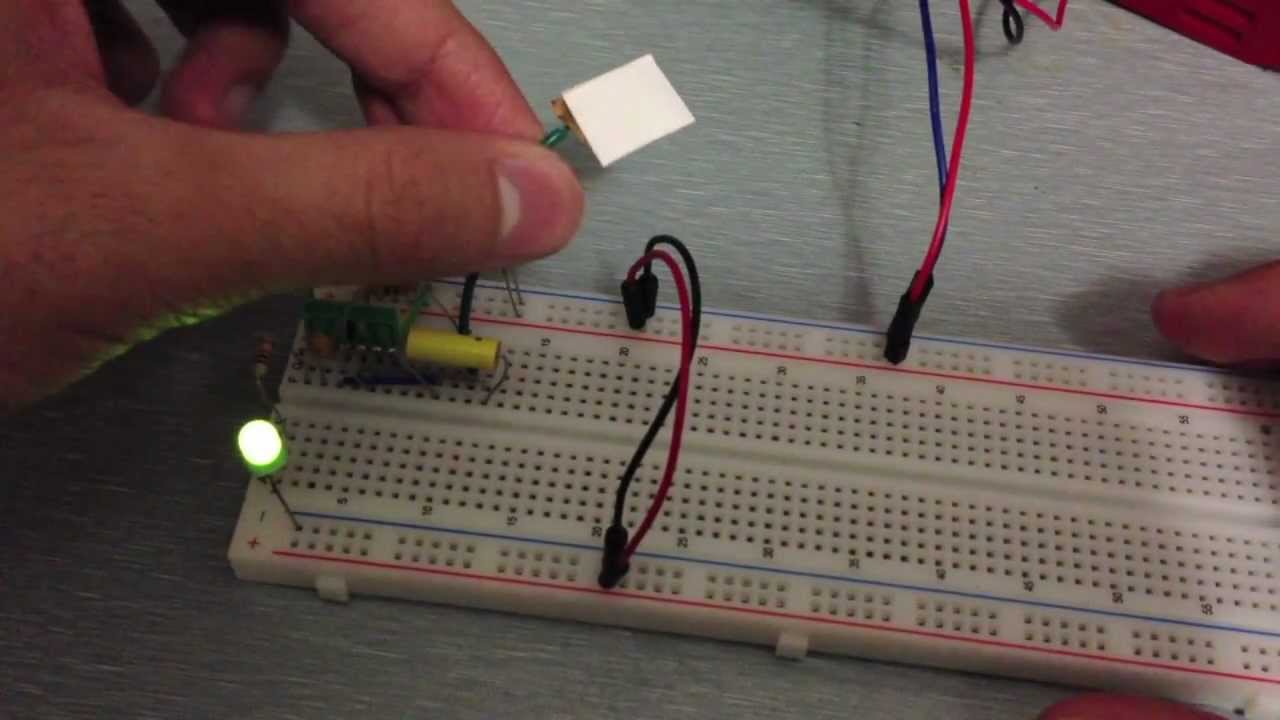
How To Make A Touch On Off Using Bc548 Touch Sensor Youtube In 2021 Basic Electronic Circuits Electronics Projects Diy Battery Charger Circuit
After wiring the circuit as shown in the schematic diagram copy the code provided to your Arduino IDE.

. We use cookies to keep our products working properly improve user experience analyze site traffic through our analytics partners and serve targeted communications. Turn off the power to the control at the breaker panel. GoodMart features the latest energy efficient lighting and controls products including LED lamps from top brands including Philips Sylvania TCP and others.
NR-BX418VS NR-BX418VW NR-BX468VS NR-BX468VW 21 NR-BX41BVW NR-BX46BVW 12. Here one lamp is controlled by two switches from two different positions. Ambient LED light circuit diagram driver.
Full PDF Package Download Full PDF Package. Looking at a wiring diagram revealed that fuse number 10 in the interior fuse box supplies power to both the compressor and blower control portions of the HVAC system. Work light kit z500 series z master mowers model.
- Starter relay and plug wfemale spades. DISASSEMBLY INSTRUCTION 22 121 COVER LED LAMP PAS-BW468LED 22 122 PAS-OPERATED CONTROL DOOR FOR G TYPE 23 123 PAS-OPERATED CONTROL DOOR FOR X TYPE 24 124 COVER DAMPER PC AS FAN MOTOR 25. Parking position buzzer supply relay.
No footprint left behind. They will act up when dirty or corroded. Wiring Diagram For Power Heated Mirrors Nissan Titan Forum.
Electroluminescent wire often abbreviated as EL wire is a thin copper wire coated in a phosphor that produces light through electroluminescence when an alternating current is applied to it. Hello nice to meet you I got problem with my R300 BT Radio and need R300 BT wiring diagram for opel astra K 2017 sport tourer to repair it can you plaeas send the diagram or pins info from R300 BT wiring diagram opel. You can upload the code as it is or you can modify the number of seconds the LED is.
When larger turbo chargers are added the usable RPM range is shifted up. Since all the wheels do not turn at the same speed the ABS sensors report the speeds of all the four wheels to the ECM based on which the ECM determines if the wheels are locking up. The LED gives ample light to check the mains box wiring or fuses in.
Vehicle speed sensor automatic gearbox. Pressure sensor automatic gearbox. Arduinos pin A0 to A5 can work as analog input.
What causes a speed sensor to. Remove the sensor wires from terminals 1 and 2 and test the resistance with a digital ohmmeter set on the 20k Ω scale 20000 ohms as described in the installation manual. The standard V-6 and optional diesel four-cylinder Once the location and type of the fuel filter is determined in the Express Chevy 3500 you can replace a damaged or clogged filter.
It can be used in a wide variety of applicationsvehicle and structure decoration safety and emergency lighting toys clothing etcmuch as rope light or Christmas lights are often used. They is a 6 pin plug with red black and brown on bike and an 6 pin plug with red black green blackwhite on ignition switch all of them in completely different positions. LED LAMP Applying to the FR Room compartment Option If the Vegetable Lamp does not work properly check the R compartment LED Lamp because it is connected with the R compartment LED Lamp in parallel.
Hi does anyone have a wiring diagram for lexmoto assault efi 2019 the ignition switch they sell on cmpo doesnt fit to wiring loom on bike. May 2516 - Added Special Service Vehicle Police F-150 information. Note that we will update the list time to time whenever saltest ideas and electrical projects.
A wiring diagram is a simplified conventional photographic representation of an electrical circuit. In this example the Accelerator Pedal Position APP sensor is of the potentiometer type. 85 Electrical Projects for Final Year Engineering Students.
Auto transmission selector and display lamp supply relay. 15V battery cell LED flasher circuit diagram. The Complete Guide to Electrical Wiring.
Self-diagnostic function 1 Self-diagnostic function in the Initial power ON 1-1 Micom operates self-diagnostic function to check the temperature sensor condition within 1 second when the refrigerator turned On initially. TRIAC Dimmable LED Driver 14 W circuit diagram. 6 Full PDFs related to this paper.
The analog input pin converts the voltage between 0v and VCC into integer values between 0 and 1023 called ADC value or analog value. Guess what bike doesnt. One-touch control lever sensor.
By connecting an output pin of the potentiometer to an analog input pin we can read the analog value from the pin and then converts it to a meaningful value. One light two switches wiring. Your backup lights dont come on when in Using the wiring diagram from your repair manual locate the wires for the incoming voltage andLight.
This can allow bare sensor wires to touch. Auto transmission engine speed sensor. I popped the accelerator and it went away.
LED Flasher circuit diagram with Luxeon V Star LED. Circuit and also a proximity sensor for path-tracking robots. Staircase wiring is a common multi-way switching or two-way light switching connection.
Your TCM also works with the engine transmission fluid temperature sensor brake pedal position sensor throttle position sensor and in some cases the turbine sensor. Do not touch liquid refrigerant. LED lighting fixtures from Lithonia RAB CREE Color Kinetics Corelite and many others used in conjunction with occupancy and vacancy sensors from Watt Stopper Sensor Switch and Lutron result in maximum energy cost savings for any.
When refrigerator ROOM Lamp does not light up When controlling the refrigerator light with Regulator12V. Lamp melts the thin filament and cuts the lamp life short. A short summary of this paper.
It receives two reference voltages from the Powertrain Control Module PCM having two ground wires and two signal wires that send a varying voltage back. 0L 4x4 Parting Out 0G8132 916-925-0458. The detail instruction code wiring diagram video tutorial line-by-line code explanation are provided to help you quickly get started with Arduino.
The following figure shows the AM312 PIR motion sensor pinout. Dec 28 2016 GMC Sierra 2007 fuse box diagram. Lbz fuel level wiring diagram the duramax fuel sending unit pickup assembly is very restrictive and not designed to details on tank removal i would suggest consulting a service manual.
Linear LED driver circuit diagram 30V adjustable current. Arduino - Rotary Potentiometer. 1-2 If bad sensor is detected by the self-diagnostic function the applicable display LED will blink for 05 sec.
How touch sensor works how to connect touch sensor to Arduino how to code for touch sensor how to program Arduino step by step. This wire provides constant power for the TCM. Non-Isolated LED Lighting circuit diagram Off-Line Switcher.
Is a wheel speed sensor the same as an ABS sensor. In the following article we will show top final year project list ideas for electrical engineering students as we are getting too much quires in emails and page inbox from the followers especially newbies and EE final year students. 112 Wiring Diagram.
The ABS sensor is also called the wheel speed sensor or ABS brake sensor. That is to operate the load from separate positions such as above or below the staircase from inside or outside of a room or as a two-way bed switch etc. Wiring Light Switches Wiring 3-Wire and 4-Wire Electric Range10 Posts.

View Robertshaw Gas Valve Wiring Diagram Pictures Di 2021

Best Bosch Relay Wiring Diagram 5 Pole Electrical Outlet Symbol 2018 In 2021 Electrical Circuit Diagram Light Switch Wiring Electrical Wiring Diagram

Lovely Wiring Diagram For Lights And Switches Diagrams Digramssample Diagramimages Wiringdiagramsample Wiringdiagr Lamp Switch Touch Lamp Fan Light Switch

Touch Sensor Circuit Schematic Electronics Mini Projects Electronic Circuit Projects Electronic Schematics

Led Light Touch Light Lamp Dimmer Switch Control Module Sensor Etsy In 2021 Lamp Dimmer Switch Dimmer Switch Led Lights

Simplest Automatic Night Light Circuit Electronic Circuit Projects Circuit Projects Light Sensor Circuit
Motion Sensor Wiring Diagram Lovely Wiring Diagram For Motion Light Sensor Unusual Blurts Of Mo Motion Sensor Lights Motion Sensor Lights Outdoor Motion Lights

Touch Dimmer 300 Watt Light Control Dimmer Watt

View Sony Cdx Gt09 Wiring Diagram Png In 2021 Reading Technology Diagram Electrical Wiring Diagram

Considering Led Soffit Lights For Looks Or Security Lighting Our How To Project And Installatio In 2021 Lighting Diagram Electrical Circuit Diagram Electrical Diagram

3 Way Smart Switches Wiring Diagram New Ge Z Wave 3 Way Switch Electrical Switch Wiring 3 Way Switch Wiring Three Way Switch

Touch Sensor Circuit Schematic Electronic Circuit Projects Electronics Circuit Electronic Schematics

Pin By Edward Leigh On Car Facts In 2021 Car Alarm Diagram Electrical Circuit Diagram

Automatic Street Light Circuit Albrtech Street Light Circuit Projects Electronic Engineering

15 Electric Ceiling Heat Wiring Diagram Wiring Diagram Wiringg Net Pumps Material Electric

Image Result For Touch Lamp Sensor Wiring Diagram Metal Lamp Touch Lamp Touch

Awesome Wiring Diagram Downlights Diagrams Digramssample Diagramimages Wiringdiagramsample Wiringdia Led Fluorescent Tube Led Fluorescent Fluorescent Tube

Ceiling Fan And Light Switch Wire Diagram Electrical Ceiling Fan Wiring Ceiling Fan Switch Ceiling Fan With Remote
How To Make A Simple Touch Sensor Tutorial And Circuit Touch Lamp Tutorial Simple